
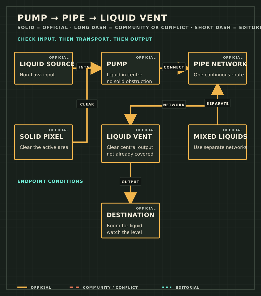
30-second source-to-destination check
- Source
Confirm that supported non-Lava liquid is still present and can reach the Pump centre.
- Pump
Clear solids from the central 2 × 2 pickup area; touching only an outer edge is not enough.
- Pipe
Trace one continuous route with no hidden gap, including both endpoint connections.
- Liquid Vent
Clear the central output area before testing.
- Destination
Leave room for the released liquid and keep the Vent above the stopping level you want.
If the transport line works but the source keeps shrinking, return to the ordinary Water source and containment checks. For Lumlings, Cryoblaster Snow, Rain, delayed buffers, or reload failures, use the separate Infinite Water supply and stability test. If the Pump, Pipe, or Liquid Vent is not available yet, confirm the Fluids unlock in the Research order guide before rebuilding the network.
Why is my Sandustry Pump not working?
The official Pump page says the building occupies 4 × 4 pixels but only the central 2 × 2 area picks up liquid. Because the Pump is non-solid, a solid pixel can enter that space and prevent liquid from occupying it. Hover with the Grabber, clear anything other than the intended liquid, and test the short network again.
Why does the Pipe look connected but move nothing?
A Pipe only carries liquid between active endpoints. Follow every segment and test the endpoint connection. Current Early Access players disagree over whether adjacent placement always connects automatically or whether some setups require Pipe drawn over the Pump and Vent. That is Version-sensitive community evidence, so compare both placements in one short visible test.
Why does the Liquid Vent stop outputting?
The official Liquid Vent page describes a central output area that stops when liquid or another obstruction covers enough of it. The whole 4 × 4 tile does not need to look full. Clear the output cells, lower the destination level, or move the Vent upward before touching the Pipe.
Why does the system work and then stop?
Recheck the changing conditions at both ends: the source can fall below the Pump centre, a solid can enter the pickup area, or rising liquid can cover the Vent output. A continuous Pipe does not create Water and does not keep an obstructed endpoint active.
Why does the wrong liquid reach the output?
The official Pipe page allows multiple Pumps and Vents on one network and says supported liquids can be distributed across its outputs. Keep each liquid on a separate network when the destination must stay pure. Lava is explicitly excluded. Steam is a gas, and current official Pipe documentation does not establish Steam transport through this liquid network; do not copy a Demo-era Steam reply as a current rule.
| Symptom | Likely cause | Check and fix |
|---|---|---|
| Pump does not take Water | No Water in the central pickup area or a solid occupies it. | Clear and refill the Pump centre. |
| Pipe looks connected but nothing moves | A segment or endpoint connection is incomplete. | Draw one short route and compare adjacent with overlap placement. |
| Liquid Vent never releases | The central output is obstructed. | Clear the face and the destination. |
| System stops after running | Source level fell or destination level rose into an active area. | Inspect both endpoints before replacing Pipes. |
| Wrong liquid output | Mixed liquids share a network. | Separate networks by liquid. |
Update record
- 2026-08-24 — Retargeted the page to Pump-not-working language and clarified Water supply, renewable supply, and transport boundaries.
- 2026-08-23 — Added the five exact symptom anchors, source-to-destination check, and endpoint-placement conflict.
- 2026-08-22 — Published the initial three-stage fluid diagnostic.
Frequently asked questions
Why is my Sandustry Pump not working?
Liquid must occupy the Pump’s central 2 × 2 pickup area. Remove Sand, Gold, or another solid from that space, then test one short Pump-to-Vent network.
Why does the Pipe look connected but move nothing?
A Pipe is transport, not an input or output. Confirm one continuous run between an active Pump and a clear Liquid Vent, including the connection at both endpoints.
Why does the Liquid Vent stop outputting?
Water or another obstruction may cover its central output area. Clear the destination and retest before rebuilding the Pipe.